
Description
NOTE: SHIPPING TO THE US IS TEMPORARILY SUSPENDED DUE TO THE CURRENT CONDITIONS THAT REQUIRE PREPAYMENT OF CUSTOM DUTIES. SORRY FOR THE INCONVENIENCE
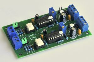
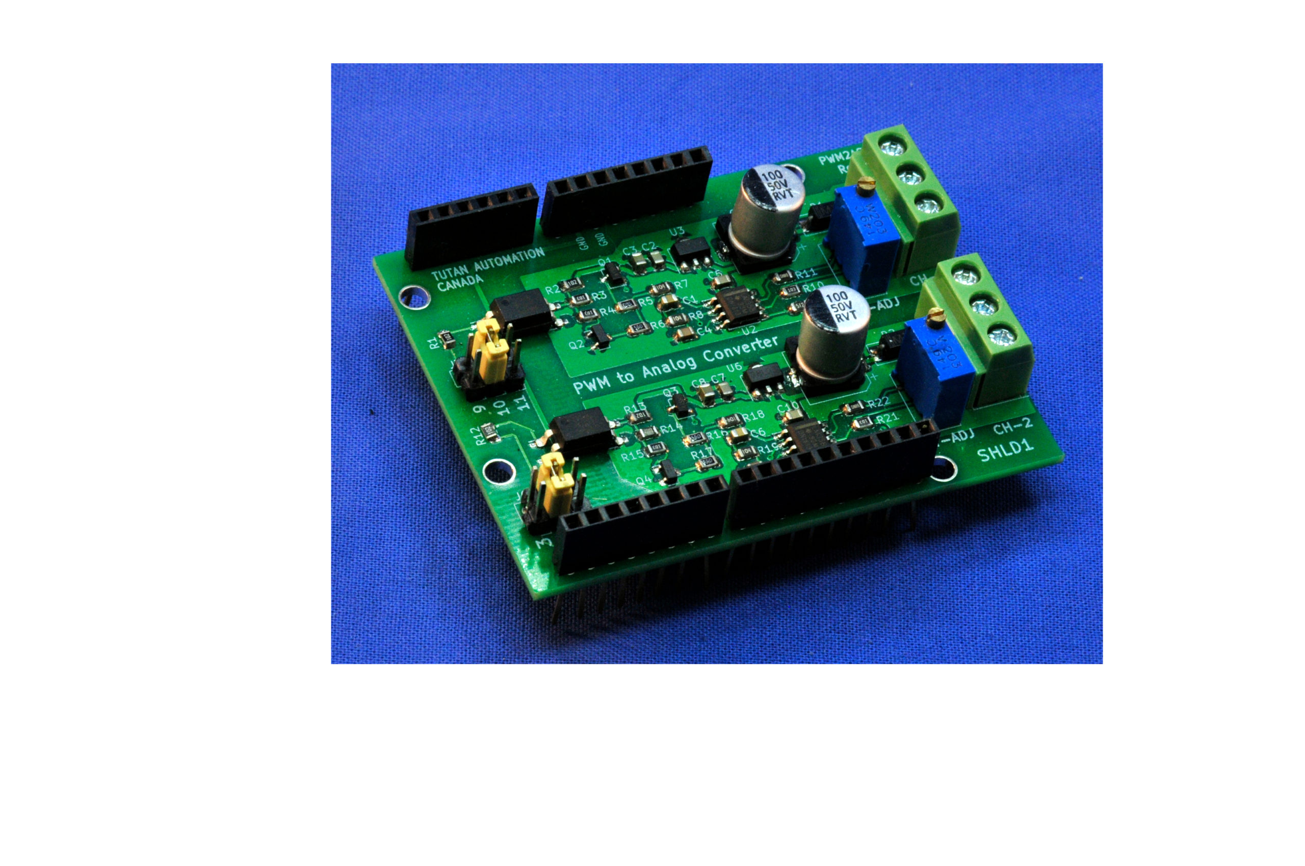
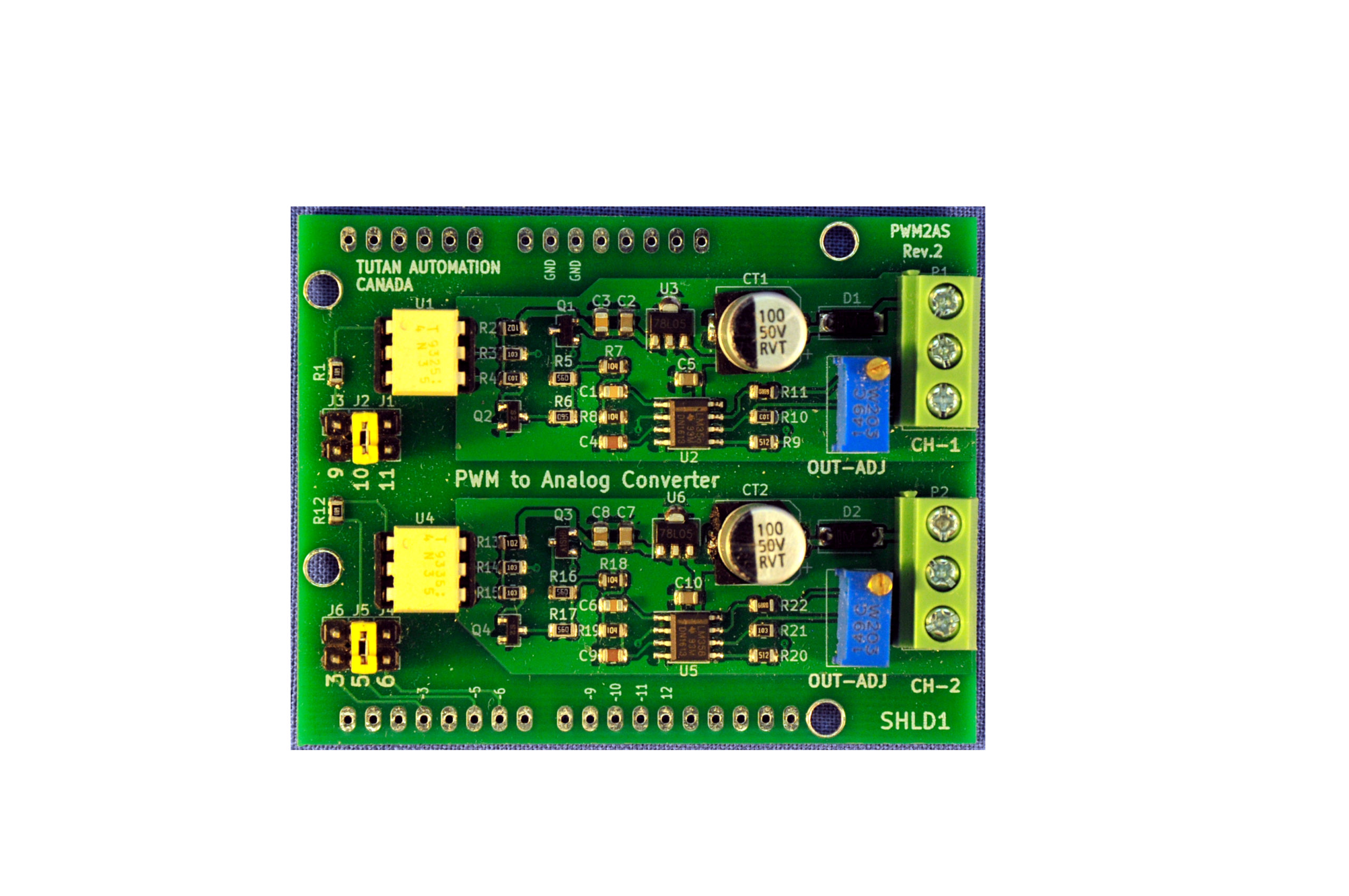
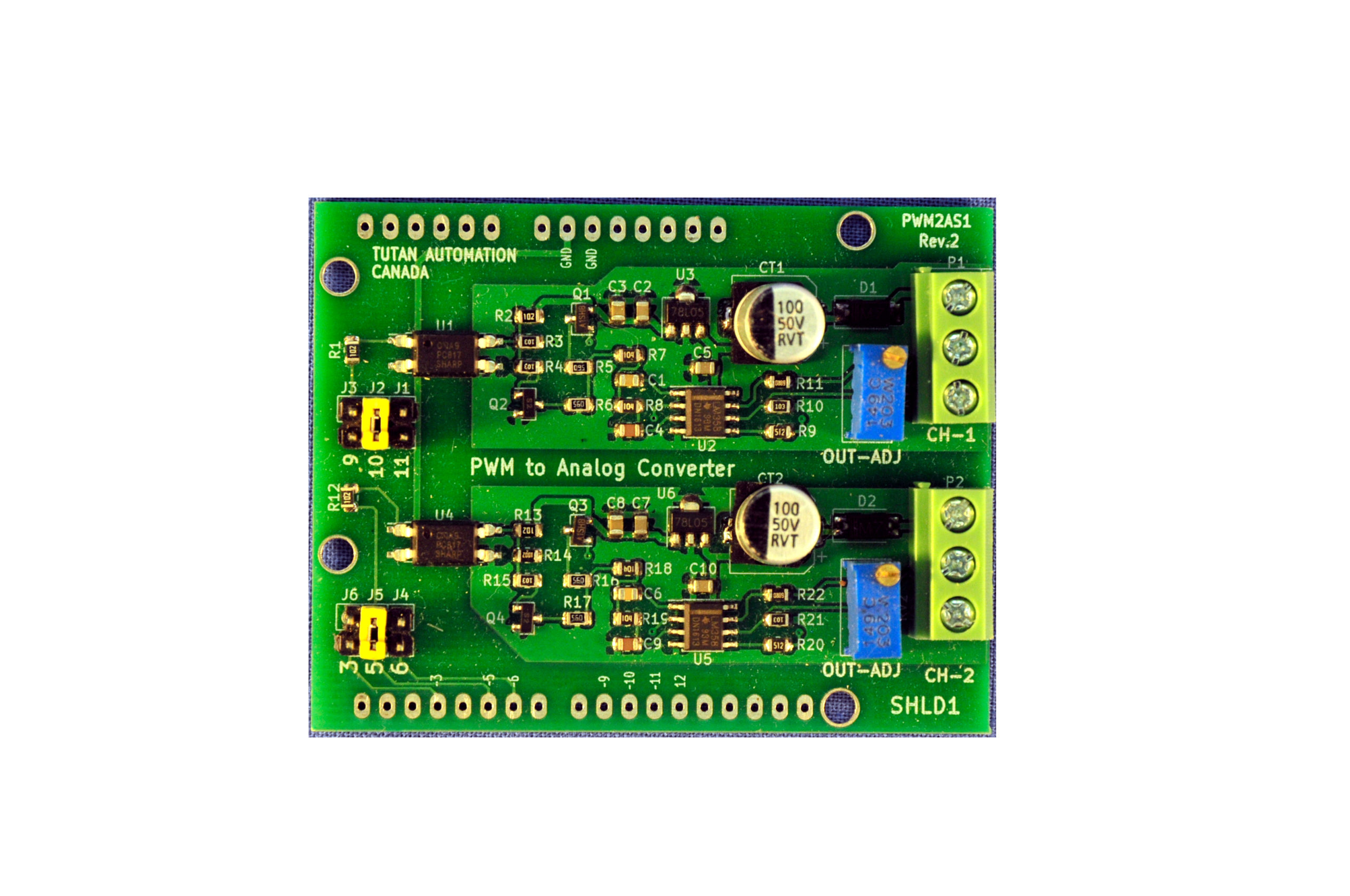
This product is a plug-in shield for Arduino compatible micro-controllers and contains two independent PWM (Pulse Width Modulation) to Analog converters. Each channel provides an output voltage proportional to the DC (Duty Cycle) of the corresponding input signal. The intended application is to provide a galvanic isolated analog signal to control proportional actuators, such as VFDs (Variable Frequency Drives), linear actuators. proportional valves and other similar devices.
Most small micro-controllers do not have real D/A converters to produce analog outputs, instead they provide PWM signals that can be converted to analog values using an LP filter. This approach is good enough to generate 0-3.3V or 0-5V analog outputs (depending on the logic level of the controller) to control small powered devices, but is not suitable to interface with high power systems, such as VFDs or Servo controllers for electric motors.
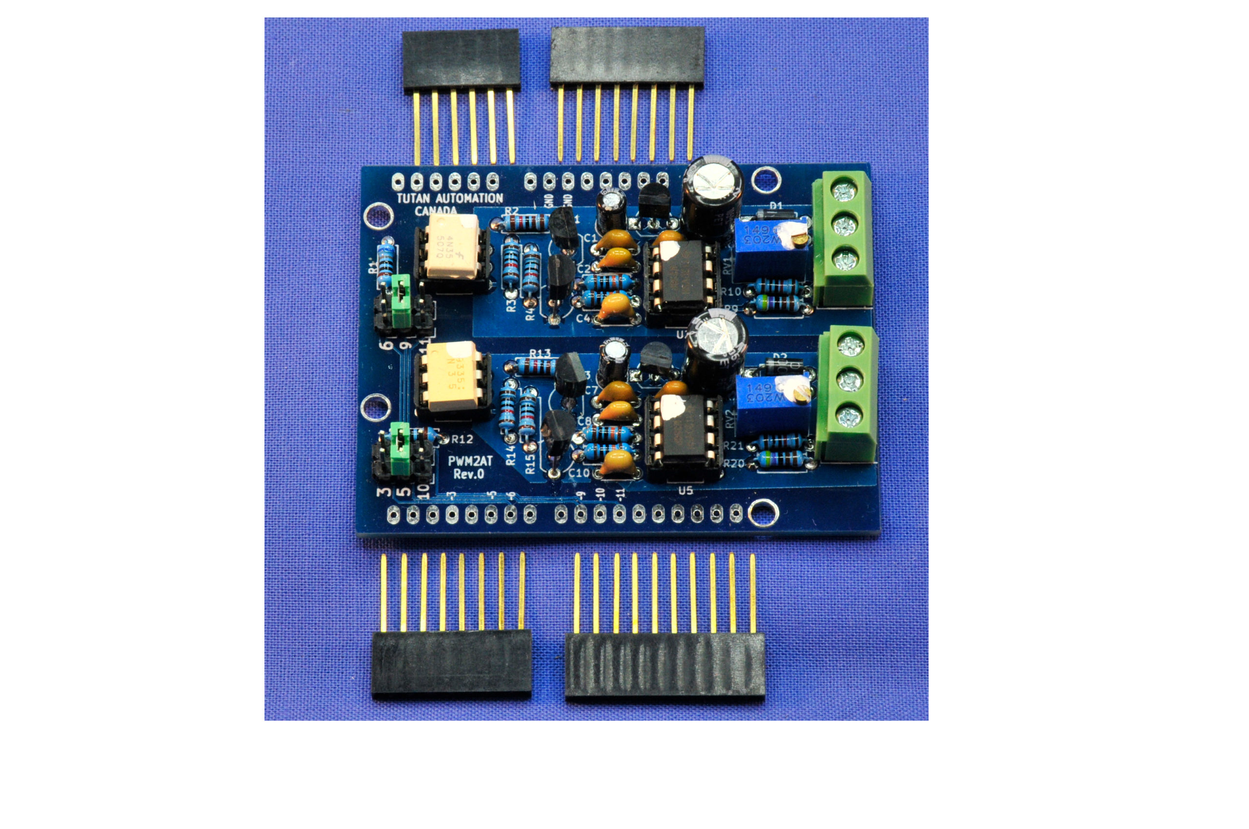
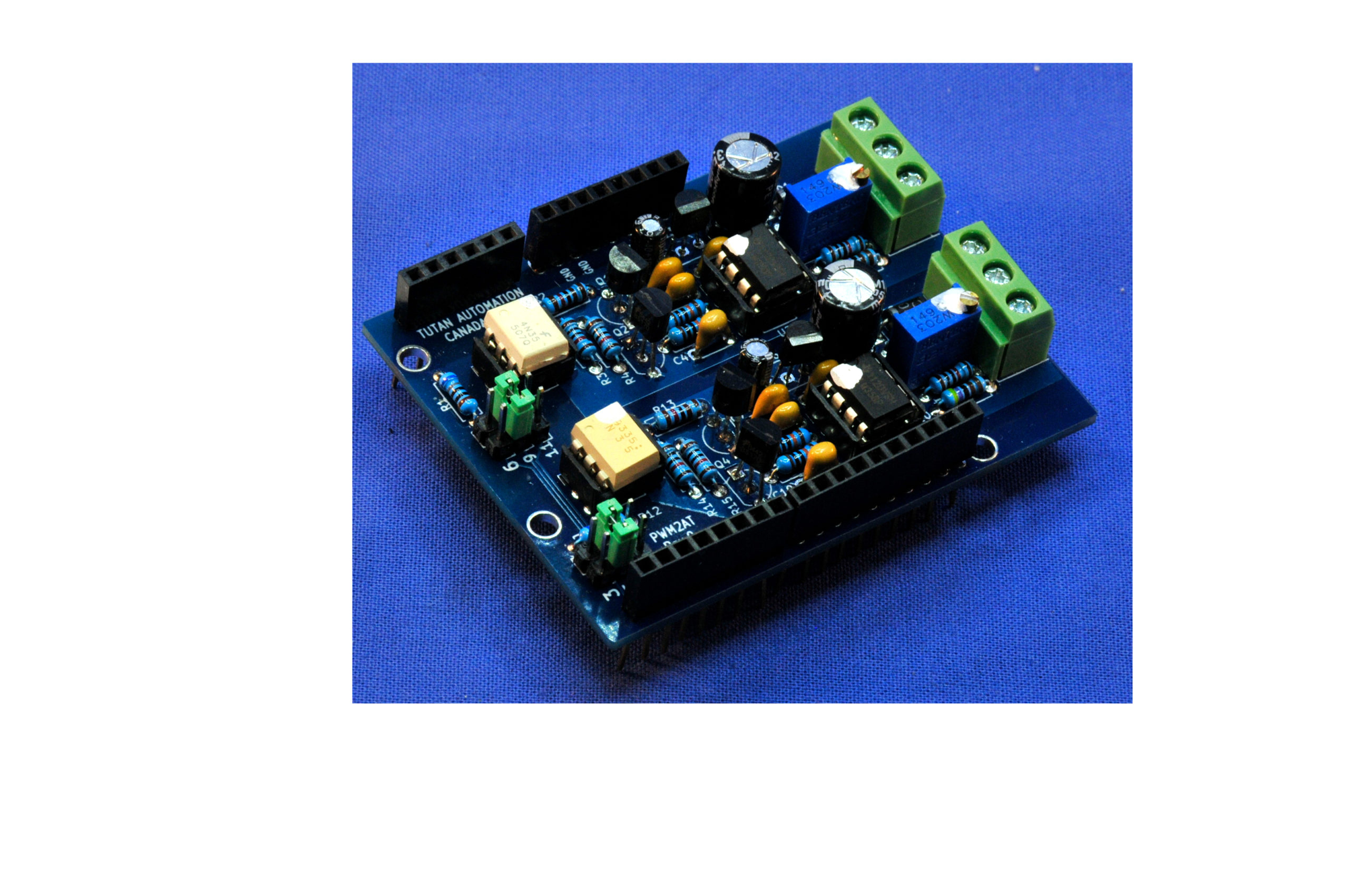
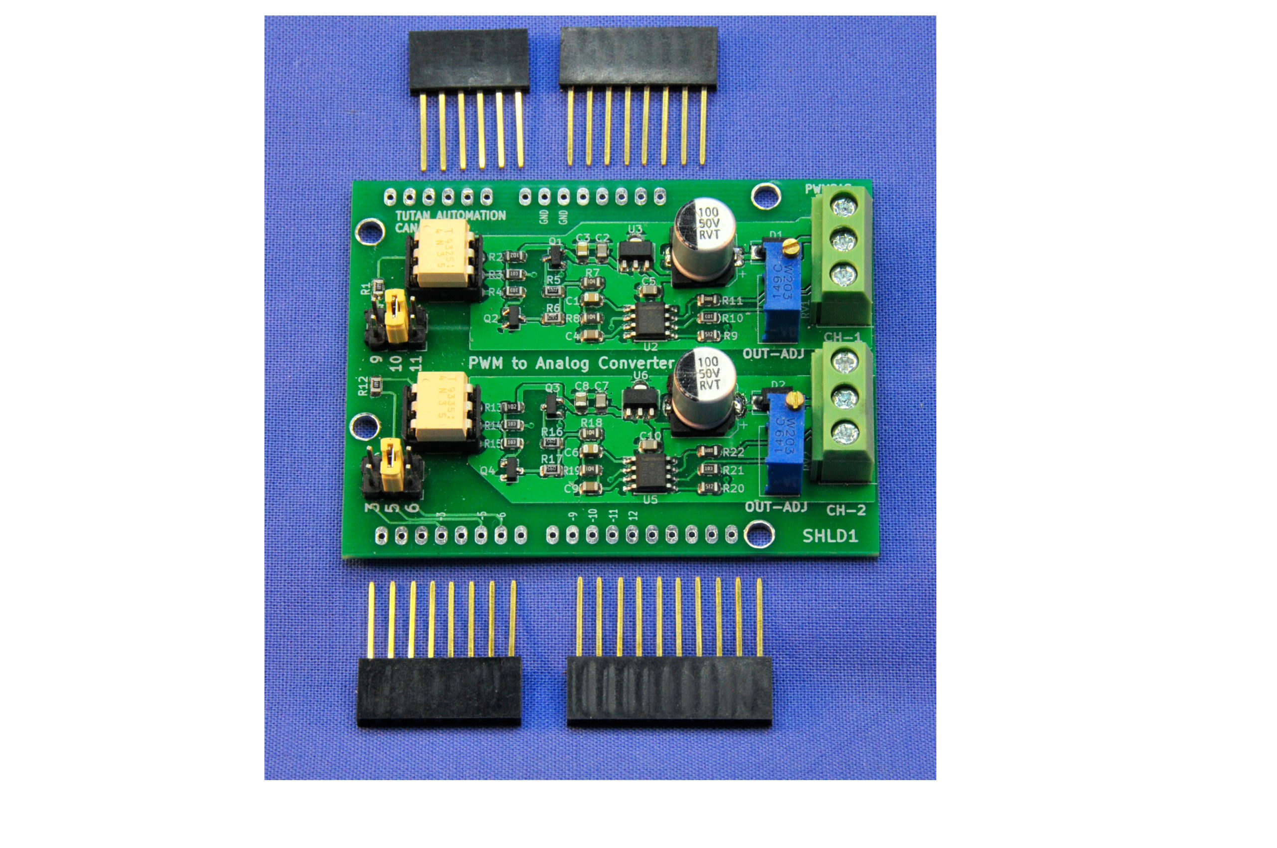
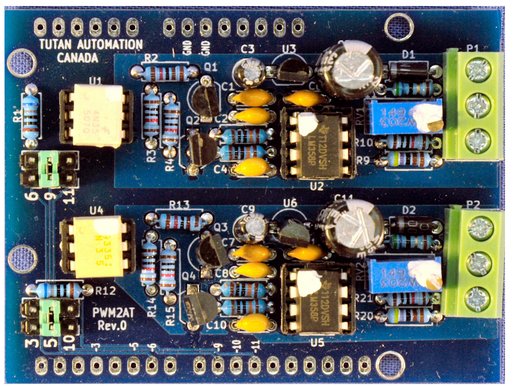
There are three optional builds available: All through hole components (THT), all surface mounted components (SMT) or quasi SMT witn only THT for the optoisolator. Select the preferred flavour when ordering.
Two jumper selectors with three position each allow the use of any of the 6 PWM pins of the Arduino UNO. The Arduino MEGA2560 has 15 PWM pins but only 6 of them can be used in this board.
SPECIFICATIONS
- Number of channels :2
- PWM input: TTL level. Max frequency 1KHz, 5mA @ 5V
- Output: Adjustable 0 to 5..15V (max. 10mA)
- Conversion system: MOSFET Totem-Pole
- Output filter: Low Pass 2 Pole Butterworth, 1.6Hz (-12dB/Octave)
- Output ripple: < 10mVpp at 500Hz
- Linearity: 1% FSD minimum
- Isolation: Min. 500 Vac
- Power: Nominal 24 Vdc (Acceptable range 10 to 30Vdc). At 10V the output level is limited to 5-6V.
- Dimensions: 2.700 x 2.100 in. (69 x 54 mm) 1.15 oz (0.033 Kg)
USAGE
Install the jumpers for each channel in the position corresponding to the PWM pin to use.
- Channel 1: Pins 6, 9 or 11
- Channel 2: Pins 3, 5, or 10
Connect the power supply to the board (15 to 30V)
Use the instruction analogWrite(pinNumber, value), where pinNumber is the pin selected in the jumper block and value is between 0 and 255.
The analog output will be: value * Vfsd / 255, where Vfsd is the maximum output adjusted and is set to 10V from factory.
It is possible to increase the output resolution from 8 bit (256 levels) to 10 bits (1024 levels) by using a different timer library, such as Timer2.h available in the Arduino IDE via the Library Manager.
CALIBRATION
Set the PWM output to 0% duty cycle (analogWrite(pinNumber, 0) and verify that the analog output is 0 to 25mV.
Set the PWM output to 100% duty cycle (analogWrite(pinNumber, 255) and adjust the level trimpot to read the required value (5 to 15V).
NOTE. You may power the board with only 10Vdc, but then the output can be adjusted only to 5-6V. This can be useful to connect commercial drives that provide only 10Vdc auxiliar power and have an input scaling parameter to use only 5Vfsd for the analog input.