Description
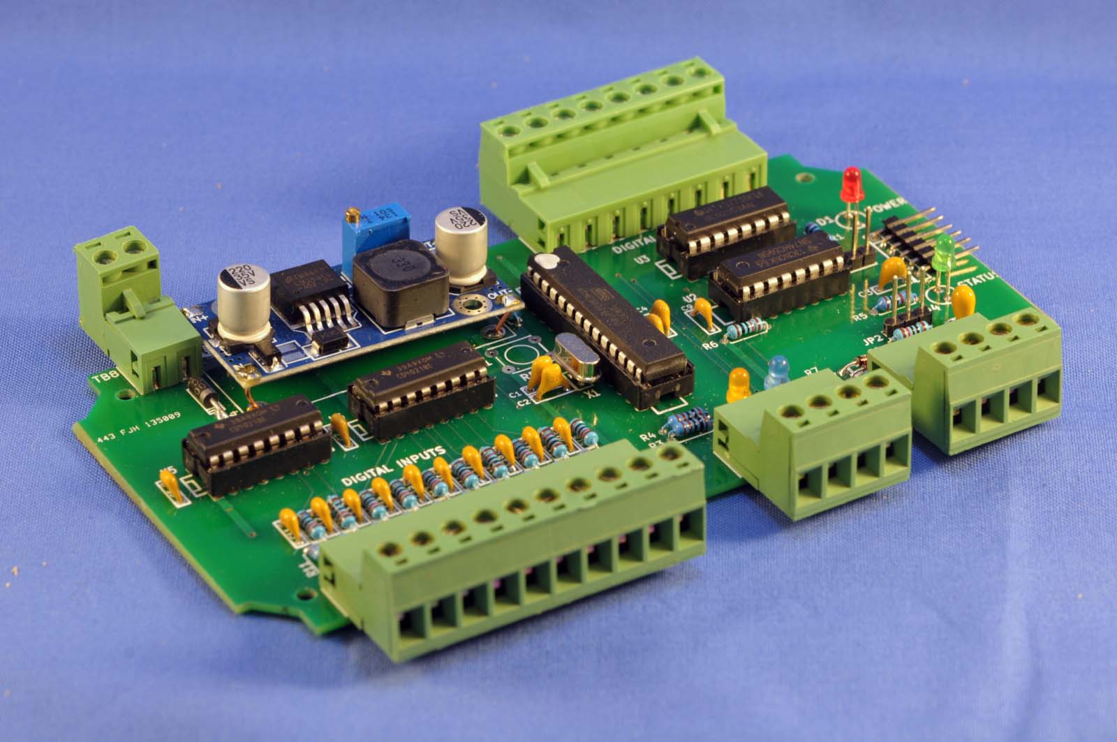
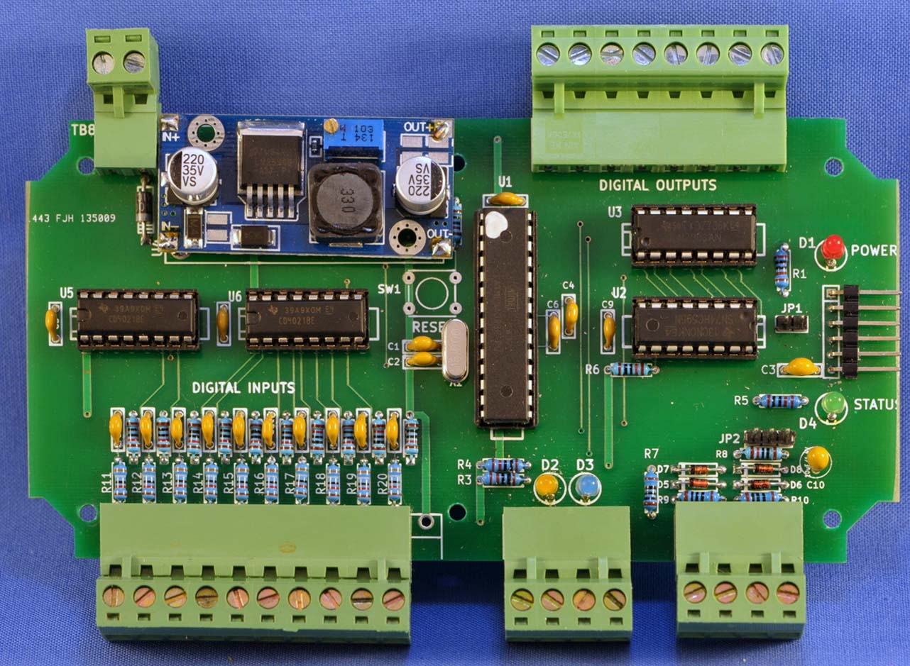
This is a rugged version of an Arduino board designed to be used as a controller for small industrial or home automation projects. Industrial controls use very often 24Vdc to power the logic, sensors and actuators. By using this standard voltage this board is easy to interface with this controls. All connections to the board are made via standard 0.2″ (5 mm) terminal blocs (fixed of plug-in type) and it can be housed in a standard plastic enclosure.
This board is specially suited for DIY fans. By using only through-hole components and a large footprint it is easy to customize by changing values of some components to fulfill different requirements.
As an example, the unit can be powered from 9 to 30 Vdc, thanks to the use of a step-down converter that provides the 5Vdc required to power the circuits and up to 2A of current for external devices (such a screen, sensors, actuators, etc. The standard logic level of 24Vdc can be modified to accept from 5 to 60V by changing the value of the input resistors. Another customization may be to replace some resistors with zener diodes to provide for a wide input level range (i.e. 5 to 30 Vdc.).
Originally the board was designed to control the operation of a paint finishing booth with two electric fans, one single or double stage gas fired burner, a temperature sensor and an external HMI with touch screen that communicates with the controller using a serial link with Modbus RTU protocol.
The controller uses input and output shift registers to provides a total of 35 I/O pins instead of the 20 available in the MCU allowing more functionality with little or no effect in performance in most applications. There are 6 direct pins to the MCU available via on-board headers, that can be used as high speed or general I/O pins.
Specifications
- Processor : ATMEL ATmega328P
- Memory: 32 KB flash, 2 KB RAM, 1 KB EEPROM
- 10 Digital Inputs, 24 Vdc, with shift register.
- 7 Digital Outputs, max. 30Vdc @ 500mA, with shift register.
- 2 Analog inputs (A4/A5) one with switchable LP filter. This inputs can be used as I2C interface instead.
- 6 direct pins to the MCU with on-board headers (D7, D8, A0, A1, A2, A3 and A4)
- 1 FTDI compatible download/monitor connector.
- 1 UART-TTL serial link adjustable 300 to 115200 baud.
- 1 ICSP header for direct MCU programming
- Auxiliary power output 5 V max 2 Amp for external devices
- Power supply: Nominal 24 Vdc, range 7 to 30Vdc (see note 1 below)
Notes:
(1) The digital inputs require 18 to 30 Vdc to operate, regardless of the power supply. By changing the values of the input resistors it is possible to use a different voltage range.
Usage
The board can be programmed using any of the free IDEs available, such as:
Example code, application libraries and community support are widely available in the web, specially in the Arduino community.
Documentation
- Assembly instructions PDF file: VM1AT-R1 Instructions
- Support library with several use examples: VM1ATR1
- Modbus server library: ModbusServer
- GNU public license: gpl-2.0
Enclosures
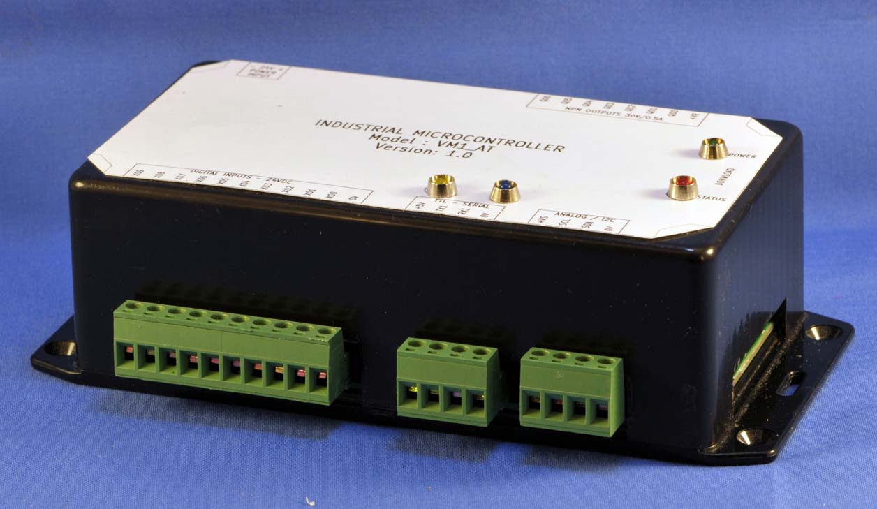
This board may be mounted in a commercial plastic box, such as Hammond’s model 1591DSFLBK. Some mechanical work is necessary to provide access to the connectors.
This box is usually availale at local distributors or may be ordered on-line from various distributors at:
Versions
This product can be ordered in three different versions:
-
- IMC002-PCB – Bare pcb without components. You have to supply all componentes to assemble the board.
- IMC002-KIT – Kit with all necessary components to assemble the board. Basic solder skills are required.
- IMC002-BRD – Fully assembled and tested board, ready to go. Loaded wiht a simple test program
